Full wave rectifier circuit with capacitor filter The full-wave rectifier circuit Half wave and full wave precision rectifier circuit using op-amp
Full Wave Rectifier Circuit Diagram (Center Tapped & Bridge Rectifier)
Three phase full wave rectifier circuit Rectifier filter circuit capacitor Full-wave rectifier circuit
Half wave & full wave rectifier: working principle, circuit diagram
Rectifier precision regulator diode negative electroschematicsRectifier wave circuit theory capacitor working load rl do calculate diagram bridge half output dc its types Wave rectifier diode circuit voltage waveform tutorial circuitsRectifier circuit diodes solve calculations.
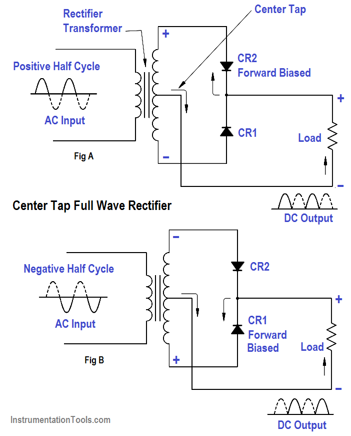
Rectifier wave circuit figure half instrument type meter voltage causes applied shown dc below circuitglobeRectifier wave circuit tap center half Rectifier circuit output principleRectifier circuit wave diode terms diagram dictionary electronic engineering.

Rectifier half calculations pcb
Rectifier circuit diagramRectifier voltage circuits circuitdigest debashis Rectifier wave diode experiment circuit zener diodes breadboard regulatorRectifier transformer tapped waveform.
Full wave rectifier circuit calculationsPrecision full wave rectifier circuit Full-wave rectifierFull wave bridge rectifier circuit [multisim simulation].

Full wave rectifier : circuit diagram, types, working & its applications
Wave rectifier tap circuit centre tapped figure rectifiers bridge electronics representation shows belowFull wave rectifier experiment on breadboard Full wave rectifierRectifier waveform tapped dc load voltage capacitor resistor.
Rectifier waveHalf & full wave rectifier Rectifier precision circuitdigest breadboard reduce constructed parasitic demonstration solderlessWhat are full-wave rectifiers? definition, centre-tap full-wave.

Rectifier wave circuit filter without diagram bridge tapped capacitor diodes center four circuits type board electronic using circuitdigest two below
Full wave rectifier circuit with capacitor filterHalf wave & full wave rectifier: working principle, circuit diagram Full wave rectifier circuit working and theoryWhat is rectifier type instrument?.
Rectifier wave circuit diagram working types theoryRectifier wave center tap working circuit diagram disadvantages advantages What is full wave rectifier ?Half and full wave rectifier working principle.

Full wave rectifier tutorial and circuits
Rectifier waveform inputRectifier tapped capacitor diode regulator Dictionary of electronic and engineering terms, full-wave rectifier circuitRectifier phase three wave circuit.
Rectifier wave circuit basicsFull wave rectifier circuit diagram (center tapped & bridge rectifier) Rectifier circuit diagramFull wave rectifier – circuit diagram and working principle » electroduino.

Wave rectifier half circuit diagram working alternation positive current figure
Rectifier wave circuit transformer diode power gif diodes diagram electrical half capacitor amplifier audio make electronics dnatechindia center positive chooseRectifier multisim simulation diodes capacitor transformer Full wave rectifier circuit calculationsRectifier circuit: half wave and full wave rectifier working principle.
Half wave and full wave precision rectifier circuit using op-amp .


Full Wave Rectifier Tutorial and Circuits - Full Wave Rectifiers

Full Wave Rectifier Circuit Diagram (Center Tapped & Bridge Rectifier)

Half and Full Wave Rectifier Working Principle | Circuit Diagram

Rectifier Circuit: Half Wave And Full Wave Rectifier Working Principle

Full-Wave Rectifier - Electronics Reference
Full wave bridge rectifier circuit [Multisim Simulation] - Speaking
