Bridge inverter circuit diagram elprocus source phase Inverter circuit bridge half basic circuits diagram transformer using center homemade tap does tutorial mini make two type similar Inverter bridge phase single ac dc load electronics tutorial
12+ Single Phase Full Bridge Inverter Circuit Diagram | Robhosking Diagram
Sg3525 full bridge inverter circuit 12+ single phase full bridge inverter circuit diagram Inverter circuit. the figure shows the single phase bridge inverter
Inverter igbt igbts salvageable
Inverter phase spwm unipolar schematic simulationInverter circuit bridge phase ic using single diagram core mosfet 5kva ac transformerless ferrite simplest driver gate pwm 2kva circuits Electric circuit of the full bridge inverter system.Power circuit diagram of a single phase full-bridge inverter.
Circuit diagram inverter bridge supply power phase single seekic600 watts full bridge power inverter circuit diagram. Simplest full bridge inverter circuitSimplest full bridge inverter circuit.

Simplest full bridge inverter circuit
How to design an inverterSingle phase full bridge inverter circuit [5] Free owners manual pdf: simplest full bridge h bridge modified sineSimplified circuit of the full-bridge output inverter..
Circuit diagram of full bridge inverter the performance of inverterInverter phase Full bridge inverter: circuit, waveforms, working and applicationsInverter bridge circuit simple transistor discrete diagram using homemade seen below.

Inverter bridge circuit homemade circuits using channel mosfets kva
Single phase half bridge and full bridge inverter circuit using matlabFull bridge 1 kva inverter circuit using 4 n-channel mosfets Inverter circuit bridge sine pure wave 1kva homemade channel kva using diagram watts 1000 make circuits mosfets circuito board projects10+ full bridge inverter circuit diagram.
Single phase full bridge inverterThree phase bridge inverter explained Single phase full bridge inverterBridge inverter circuit half ic simplest ir2110 homemade simple using.

Pwm bridge inverter phase single control figure which technique used
Inverter circuitInverter circuit basic circuits high bridge diagram square wave tutorial types explanation oscillator push pull prohibited dangerous incorporated regarding designing Inverter harmonic judge presentInverter simplified.
Inverter phase bridge three circuit diagram using power explained thyristors six figure electrical diodes shows below simpleSchematic of a full-bridge inverter Bridge inverterSg3525 inverter circuit bridge diagram using bootstrap mosfet homemade circuits channel capacitor mosfets pdf schematic try post investigate transformer drive.

How to design an inverter
Circuit inverter11 the power circuit diagram of a three phase bridge inverter using six H-bridge inverter circuit using 4 n-channel mosfetsA). circuit diagram of simple full-bridge inverter with 0 o and 180 o.
12+ single phase full bridge inverter circuit diagramBridge inverter half phase single circuit using matlab diagram square circuitdigest two power voltage same waves complimentary purpose pwm having Schematic diagram of single phase full-bridge inverter circuitInverter circuit phase output waveforms principle.


H-Bridge Inverter Circuit Using 4 N-channel Mosfets - Homemade Circuit

Single Phase Full Bridge Inverter - I Can't figure out which PWM
Free Owners Manual PDF: Simplest Full Bridge H Bridge Modified Sine

Schematic diagram of single phase full-bridge inverter circuit
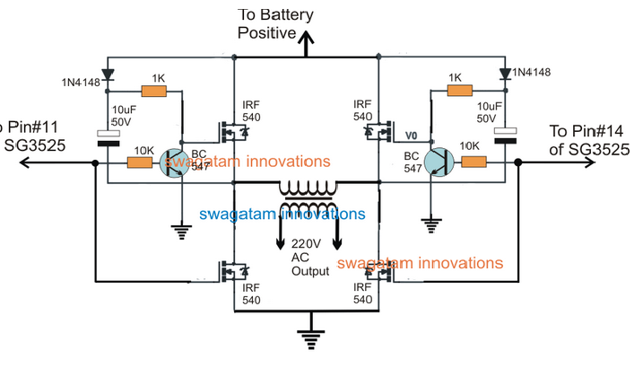
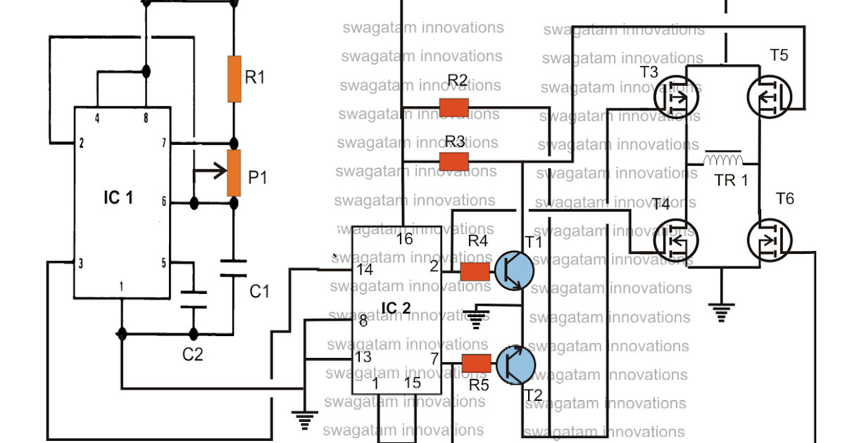
SG3525 Full Bridge Inverter Circuit

a). Circuit diagram of simple full-bridge Inverter with 0 o and 180 o

Simplest Full Bridge Inverter Circuit - Homemade Circuit Projects
